DIY ramses_esp dongle
Heat recovery fans and Honeywell’s heating control “talk” to your thermostat and remote control via radio signals at 868MHz. Several manufacturers use a controller (PCB) from Airios from Eindhoven, NL.
If you want to control these devices in your home from HomeAssistant, you’ll need a dedicated receiver/transmitter, which you can buy ready-made, e.g. the Indalotech ramses_esp approx. GBP 45 + postage, or you can assemble it yourself from 3 simple components.
In this post I explain how I did that.
Hardware
Required parts:
- ESP32-S3-N16R8 WROOM-1 dev board w/pins: €10-€15, for sale here and here (N16R8 means 8MB PSRAM and 16MB FLASH)
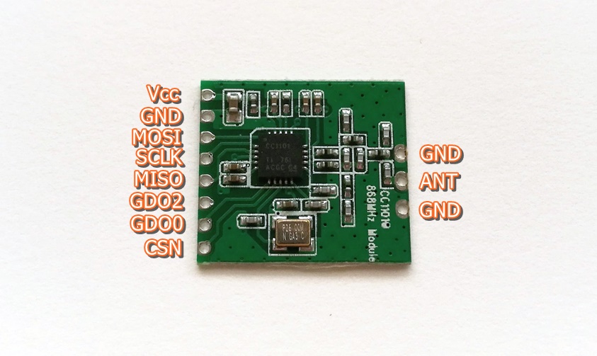
- CC1101 868 MHz transceiver: €5, I ordered mine here
- 170-hole mini-breadboard €1
- 6x Dupont jumper cables male-male 10cm €1
- USB-adapter, e.g. an old iPhone charger.
- USB-C cable, 10 cm long
Total price incl. P&H: ca. €25.
Connections
CC1101
Solder the spiral antenna on the middle holw on top of the CC1101 PCB.
Cut off the plugs on 1 side of 8 Dupont cables, strip the cables 3 mm and solder them to the 8 connections on the CC1101 PCB.

ESP32
Stick the ESP32 onto the mini breadboard, offset to the left. The holes are interconnected horizontally (number rows), so if you plug a Dupont cable into the breadboard next to a pin, it is connected to that pin.


Firmware
The “stick” needs software, which you can “flash” to it yourself from a Mac or PC with esp-idf.
Download the latest version of IndaloTech ramses_esp firmware and the instructions.
I flashed the firmware code from my iMac via USB-C to the ESP32 with the Terminal program esp-idf. Open a Terminal window in the folder where ramses_esp was downloaded, and tap:
idf.py menuconfig
...
Loaded configuration '/Users/me/esp/ramses_esp/sdkconfig'
Type Escape to leave menu item, Q to exit the menuconfig application.
You still have to adjust these connections in the ‘ramsesesp’ build before flashing, because pins 35-37 as used in the code of Indalotech, are already in use for the PSRAM on this ESP32-S3. We change the other pins so that we have them all close together on one side of the PCB. You can adjust this in the _esp-idf configmenu terminal program. In the terminal, type “idf.py menuconfig,” use the arrow keys to move down to Component Config + Enter, and then go to C1101 Configuration + Enter. Set the GPIO pins as follows:
| CC1101 | ESP32-S3-NR16RN8 | color |
|---|---|---|
| VCC | 3V3 | white |
| GND | GND | black |
| MOSI | 13 | brown |
| SCLK | 12 | red |
| MISO | 11 | orange |
| GDO2 | 10 | yellow |
| GDO0 | 9 | green |
| CSN | 8 | blue |


idf.py flash
The flash command includes a build and tries to find the serial-over-USB port automatically.
To exit idf, type Ctrl-]
Via USB
Write your Wi-Fi settings on the ESP32 using a serial terminal according to the instructions. On macOS, this can be done with the ‘screen’ program.
If you’re going to plug the ramses_esp into the USB port of your HA box, you’re done now. Set the USB port in the Ramses RF configuration > Serial Port. Restart HA, and you should see messages in the System Log.
Via MQTT
If you want to place the dongle closer to your ventilation instead of next to your HA box but elsewhere in the house, you can forward the received Ramses-II messages to HA via the MQTT protocol. Check the Ramses RF Wiki to see how to set that up in the integration.
Also set the MQTT settings as linked to Home Assistant, e.g. with the Moquitto App.
Finally, also set the NTP (time server), because otherwise your messages will have a very old date, and Ramses RF will not work.
Note: I still have to check if you still need to adjust these connections in the ramses_esp code, in my note it says that the standard pins are already in use by the PRAM.
Ready to run
Finally, connect the ESP32 to the 230V adapter via one of the two USB-C connections.
Good Luck catching those packets!
Enjoy Reading This Article?
Here are some articles you might like to read next: